|
| Electric Vehicles | Overview | FAQ | Efficiency Analysis | Driver Resources |
Tom & Cathy's RAV4-EV
LED Interior Lights
Last Updated July 5, 2009
In another shameless copy of one of Darell's ideas, we decided to convert the interior lights to LEDs, with a microcontroller to turn them off automatically in case we forget.
As long as I was designing boards for
RAV4-EView, I made a couple boards
for the front light:
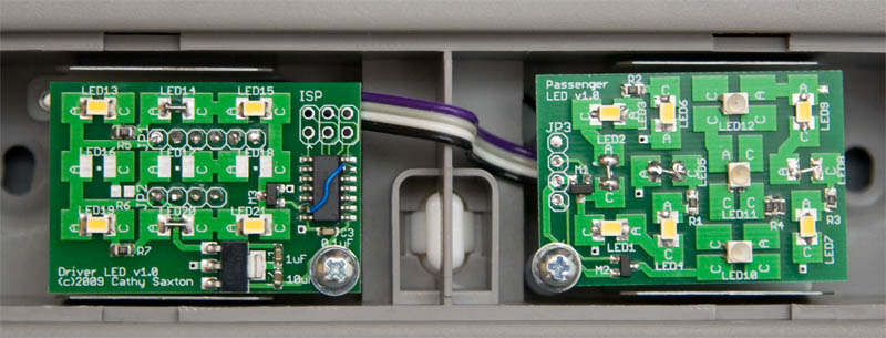
The board on the driver side (left) has the microcontroller and voltage regulator. The
yellow rectangles are the white LEDs (4 left, 6 right -- more on that later). Also on the
passenger board are 3 red LEDs (the white components in the seconds column from the right) so
that the passenger can read with minimal impact on the driver's night vision.
| LED lighting when (driver) door open | Optional red LED light on passenger side | |
 |
 |
The red LEDs will be used instead of white when (only) the passenger map light is on and the 'door' switch is in the 'off' position.
After 4.5 minutes of no activity, any lights that are on will dim to 50%. Thirty seconds later they'll shut off. The dimming is intended as a warning; simply toggling any button will bring the level back and reset the timer.
Lighting Analysis
The first version of the boards each had six warm white LEDs. Turning on all twelve LEDs used just over 1 Watt, versus the two original 8-Watt incandescent bulbs.
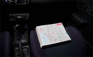
Here are pictures of the lighting when the door is opened. We used a white-balance card to adjust the color, but the exposure is the same in both photos (4 seconds at f/4.0 and ISO 400).
| Lighting when (driver) door is open | ||
| Original incandescent bulbs | LED lights (6 on each side) | |
 |
 |
|
Yes, the LED lights are noticeably brighter than the original lights. Whoops. Fortunately, that's a solvable problem!
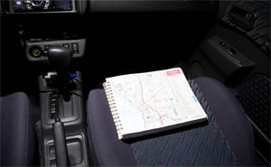
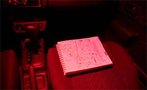
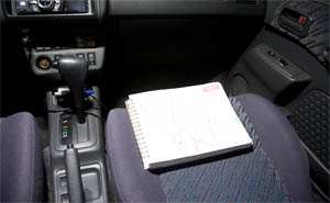
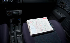
Here's a comparison of the brightness when just the passenger map light is on. With the original bulbs, that's actually brighter than the light when the door is open -- the issue is that when only the door is opened, there's a diode taking some of the voltage from the bulb; when the map light is turned on, the bulb gets the full voltage. These have the same exposure as the photos above.
| Lighting when passenger map light is on | ||
| Original incandescent bulb | LED lights (6) | |
 |
 |
|
Notice that the map is washed out in the photo on the right, indicating that it's a bit brighter than the original.
Adjusting the Brightness
There are multiple options for dimming the LEDs. For experiments, the easiest was a code change to use PWM (pulse width modulation). The basic concept is to cycle the LEDs on and off very quickly; I'm using about 1 kHz. The amount of 'on' time controls the brightness, e.g. 80% 'on' time results in about 80% of full brightness.
For the final result, I figured I might be able to remove a pair of LEDs (reducing from 6 to 4 LEDs), so I set the PWM to create a brightness of approximately 67% of full. Due to some other issues, I also ended up re-soldering a new board for the driver side, so I just used 4 LEDs there (turned on to full brightness).
The experiment worked well. The 2/3 brightness level seems appropriately bright, and the four full-brightness LEDs on the driver side are the same apparent brightness as the six 67% brightness LEDs on the passenger side. Photos coming later...
The red LEDs also seemed a bit bright; my long-term plan is to dim them by reducing the current (by increasing the series resistor), but for now they are also dimmed via PWM.
More Techie Details
You may notice (in the photo at the top of the page) that there are some places that look like they should have LEDs but don't. I designed the boards with the ability to hold up to nine white LEDs per side, in three strings of three LEDs each (plus a current-limiting resistor for each string). The first experiment used six LEDs, configured as three strings each containing two LEDs (plus a resistor). The third potential LED location in each string is replaced by a wire. On the new driver-side board, I also skipped one string, so there are three unpopulated locations corresponding to the unused string.
The LED strings are connected to the battery's 12V. The microcontroller runs at 3.3V and switches the LED strings on and off via N-channel MOSFETs. When idle, the assembly uses around 200 microamps of power. (A radio can use up to about 10 milliamps, or about 50 times what I'm using.)
Observant readers may notice that there is a small blue wire snaking over the microcontroller. This is because I didn't originally have the driver-side LEDs controlled by a pin with automatic PWM output. That's fixed in version 1.1.
I'll probably put the schematic here when I'm done with the version 1.1 updates. Check back later...
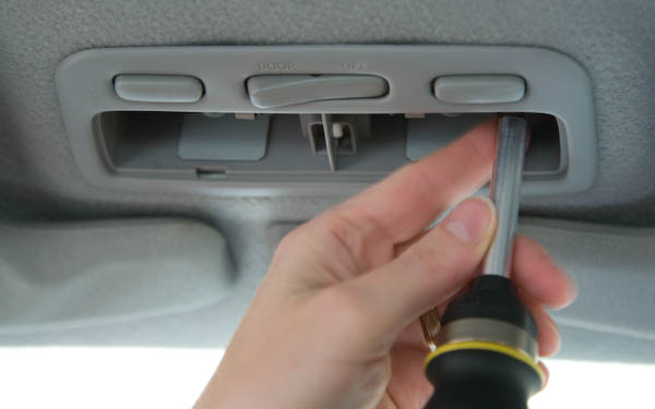
Assembly
If there's interest from others in doing this, I can put up more detailed instructions. For the moment, this will at least give you a taste of the process.
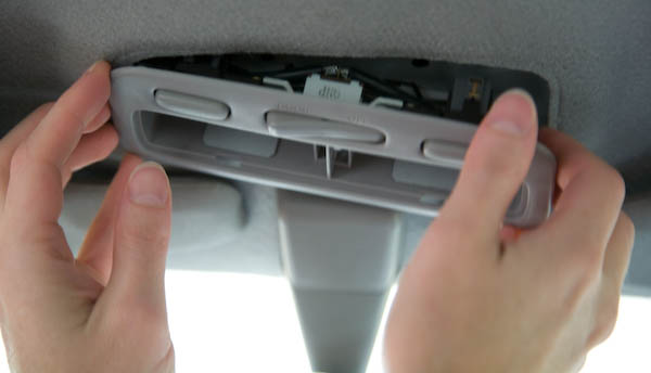
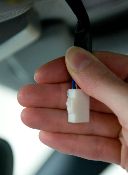
These first several photos show the removal of the housing.
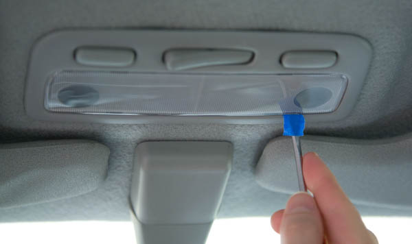
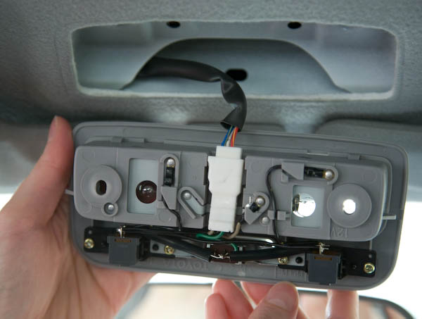
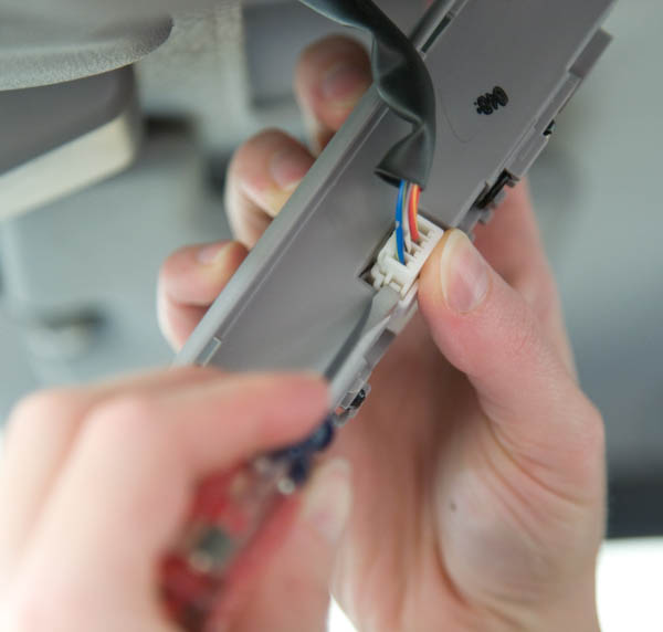
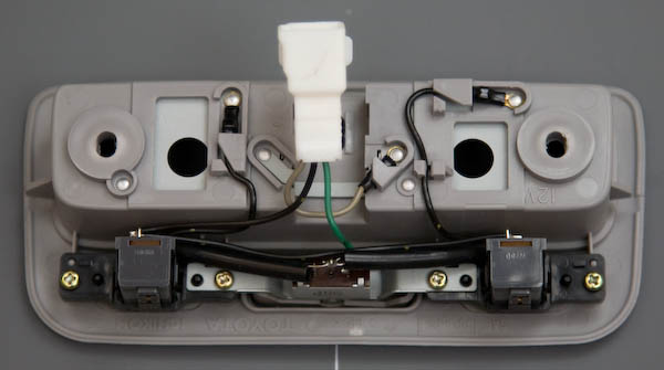
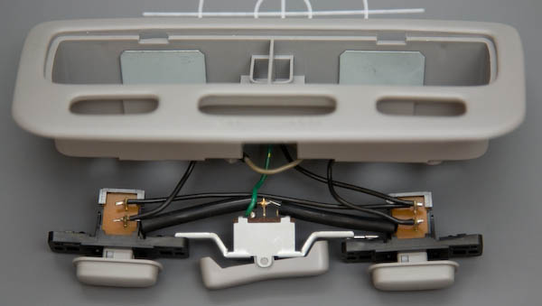
These two photos show the housing before rewiring.
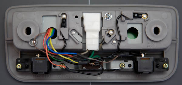
This photos shows the housing after soldering connections to my boards.
| Electric Vehicles | Overview | FAQ | Efficiency Analysis | Driver Resources |
|
©1996-2026 Tom and Cathy Saxton. You may not copy or reproduce any content from this site without our consent.