|
| Electric Vehicles | Overview | FAQ | Efficiency Analysis | Driver Resources |
Tom & Cathy's RAV4-EV
Keyless Entry
Last Updated April 29, 2009
We were surprised to discover that Toyota didn't include keyless entry for the RAV4-EV. It was high on our list of things to remedy. Cathy had a terrible experience with an installation on a previous vehicle done by one of the car accessory chains (among other things, they disabled the power to the convertible roof and gouged the dash). So, she was determined to do the installation herself so that it would be done right!
Our goal with this page is to provide details to assist other RAV4-EV owners with a keyless entry / alarm installation. For various details, you'll need to refer to the Electrical Wiring Diagram (EWD) for the RAV4-EV. We got ours from the Toyota Technical Information System. (Thanks to Darell for recommending this source.) The EWD has information on where to find the wires to which you'll need to connect, and you can use it to understand how we're tapping into the car's system. The EWD references below include the page numbers from the 2002 RAV4-EV EWD.
Our experience was that after-market keyless entry / alarm systems are pretty similar, right down to the translated-from-another-language installation instructions. That can make it challenging to figure out how to hook things up since it's not always clear exactly how a signal is used. Hopefully, the descriptions of the alarm signal lines below will be sufficient to help you identify how they correlate with your system.
At the end of this page (in the Wiring section) is a table that summarizes all the connections you'll need to make between the RAV4-EV and alarm system. All of the connections are listed there, but you'll need to understand the explanations between here and there (and some information from the EWD) in order for that table to be useful.
And, of course, this page wouldn't be complete without the standard disclaimer: you can use this information at your own discretion; we take no responsibility for anything you may do that damages you or your vehicle. Please hire a professional if this seems too complex!
One further caveat: this page is created from notes we made as we planned and installed the system. It's possible that we neglected to record something important or made an error transcribing to this page. We've double- and triple-checked, but please do your own checking! Also, if you use these notes and find them accurate (or have corrections), please email your thoughts to [comments].
General Notes
The RAV4-EV uses negative triggers for things like doors lock/unlock and parking lights, i.e. the car connects the appropriate signal line to ground to trigger the relay. The alarm install manual will have instructions for both negative trigger and positive trigger vehicles. You always want the negative (-) options.
Wiring according to the instructions below will result in all doors being unlocked with a single press of the unlock button on the remote. Many systems offer an option of 2-stage unlocking, where the first press just unlocks the driver door and a second press unlocks all doors. That behavior would require hooking the main unlock signal up to just the driver's door and making an additional connection for the second stage (specifics are left as an exercise for the reader :-) ).
To splice into the existing wires, we used Radio Shack's "Tap-In Squeeze Connectors":
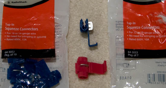
One side of the connector has a pass-through (the top part of the blue connector); that slides onto
the existing wire. The other side has a 'stop' near the middle (the lower hole in the blue
connector); the existing wire goes into that slot. When you
squeeze with pliers, the metal piece moves into the connector and cuts through the wire insulation
to make an electrical connection. Then you fold the plastic flap (L-shaped piece at the bottom of the
blue connector) over to cover the exposed metal. The red connector functions the same way; it's
just for a smaller wire.
Our alarm system has two connections for the parking lights. As expected, there is an "output" signal that connects to the car's parking light circuit. In addition, there is an "input" signal; this was documented in our system's installation manual as a line that should be connected to either power or ground as appropriate for the vehicle. This determines what voltage level is sent to the parking lights to turn them on, which for the RAV4-EV needs to be a ground signal.
A Brief Tour of the EWD
Read 'How to Use This Manual' (section B) to understand the notation. Wire color abbreviations are on page 5.
'Relay Locations' (Section F) identifies the location for panels and the connectors within them. Pages 20 and 28 apply to this project.
'Electrical Wiring Routing' (Section G) shows the locations for components, harness connections, and ground points. Page 50 has interesting locations, and page 51 has details on the connectors (including pin numbers).
Section H has all the system circuits in nice colored drawings. These are the pages referenced in the connections section below.
Notation
The notation here attempts to mimic the EWD notation. In the table below, the Symbol column shows an example connector name, with x representing a letter and n representing a number. Pin numbers are indicated with '#'. The EWD page is where you can find the connection's location in the car.
| Symbol | Connection | EWD Outline Shape | EWD Page |
| \Ix/ | ground point | triangle | 50 |
| #[Ixn] | harness connector | rectangle | 50 |
| #(1x) | panel connection | oval | 28 |
Understanding the Connections
This section explains what connections need to be made between the alarm system and the RAV4-EV. As you identify each connection in the EWD circuit, make a note of the wire color it specifies.
| EWD section | EWD Page | RAV4-EV Functionality | Alarm Details |
| Door Lock Control | 130 -131 |
When the Lock button is pressed, 11[IB1] connects to ground. | Since the signals connect to ground to trigger the lock/unlock relays, you will connect these to the negative (-) lock/unlock pulse connections on the alarm. |
| When the Unlock (all) button is pressed, 10[IB1] connects to ground. (When unlocking only the driver's door, 13[IB1] connects to ground.) | |||
| Ground point \IA/ is shown here (and various other places). | The alarm's ground signal will connect here. Also, the alarm's parking light "input" will connect here since a connection to ground is needed to turn the lights on. | ||
| Taillight | 110 -111 |
When the parking (tail) lights are turned on, 'C15 Light Control switch' connects 3(1G) to ground. | The alarm's "output" for parking lights will connect to 3(1G). |
| Horn | 154 | To honk the horn, 6[IA2] is connected to ground. | Connect 6[IA2] to the horn output, not the siren output. |
| Interior Light | 118 | 'P8 Personal Light' is connected to 3[ID1]. When either front door is opened, 3[ID1] is connected to ground. | See comments below for details. |
| 'I4 Interior Light' is connected to 2[ID1]. When either rear door or the cargo door is opened, 2[ID1] (and 6[IC1]) is connected to ground. | |||
| Constant (unswitched) power is available at 5[ID1]. (This connects internally to various panel connections as well.) | Connect this to the alarm system's power input. | ||
| Radio and Player | 178 | Switched power is available at 4(1E) and 3(1H). (These connect internally to various other panel connections as well.) | Connect to this signal to the alarm's 'ignition input.' This connection is just used to detect a key turning in the ignition; it uses minimal power. |
Interior Light comments:
The two Interior Light connections above serve two purposes. As input to the alarm system, they indicate when a door has been opened (the voltage drops to ground). In addition, the alarm can output a ground signal to turn on the interior light; this is done when the system is disarmed.
We tried to have both interior lights come on when the system was disarmed, but there wasn't enough power; both lights were very dim. So, we wired this to have just the front light come on when the system is disarmed.
The signal line to detect an open door needs to connect to both the front and rear door circuits. Connecting to both with a simple wire would tie those circuits together from the car's standpoint; that would result in a change in how the interior lights behaved, which we wanted to avoid. (Opening either of the front doors should turn on just the front interior light; opening either rear door or the cargo door should turn on just the rear interior light.) To solve this problem, we added a couple of 1N4001 diodes (covered with shrink tubing).
Since the signals connect to ground to indicate an open door, you will need to use the negative (-) door trigger input on the alarm. Connect that input to the anodes of two diodes. Connect one cathode to 3[ID1] (front) and the other cathode to 2[ID1] (rear). Also connect 3[ID1] (front doors/light) to the alarm's interior light output.
Wiring!
For each connector, look at the EWD to find its location, shape, color, and pin configuration. Find the connector, then trace the wires from it until you find a convenient place to splice in. Note that it is not safe to connect to a wire just because it's the right color! Multiple different signals use the same color wire.
Here are pages with connection details in the 2002 RAV4-EV EWD:
- Page 28 shows the #(1x) panel connectors. The panel location is shown on page 20.
- Page 50 shows the location of #[Ixn] wire harness connectors. Connector details are on page 51.
- Page 50 shows the location of ground point \IA/.
| Car Connection | Alarm Connection |
| 6[IA2] | Horn output |
| 10[IB1] | Unlock output (negative trigger) |
| 11[IB1] | Lock output (negative trigger) |
| anodes of diodes 1 and 2 (e.g. 1N4001) | Negative (-) Door Trigger input |
| 2[ID1] or 6[IC1] | cathode of diode 1 |
| 3[ID1] | cathode of diode 2 and Interior Light output |
| one of 5[ID1] 3(1A) 9(1B) 7(1G) 22(1I) 5(1J) | 12V constant (unswitched) source |
| one of 5(1B) 4(1E) 2(1H) 3(1H) 2(1M) | Ignition input |
| 3(1G) | Parking Light output |
| ground, e.g. \IA/ (wire or screw) | Parking Light input |
| ground, e.g. \IA/ (wire or screw) | Ground |
| (optional connection to car, not documented here) | 2nd channel output, Negative Instant input, Siren, Starter Interrupt |
| (not connected in RAV4-EV) | Positive (+) Door Trigger input |
That's it! Good luck and have fun!
| Electric Vehicles | Overview | FAQ | Efficiency Analysis | Driver Resources |
|
©1996-2026 Tom and Cathy Saxton. You may not copy or reproduce any content from this site without our consent.