|
| Electric Vehicles | Overview | FAQ | Efficiency Analysis | Driver Resources |
Tom & Cathy's LEAF
LED Charge Port Light
Posted January 8, 2013
Inspired by Travis's charge port light, we added LED lights to our LEAF's charge port, with a microcontroller to turn them off automatically after a few minutes.
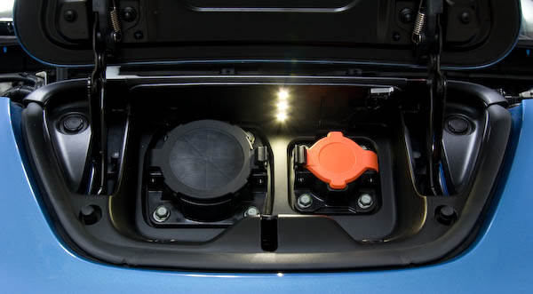
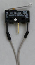
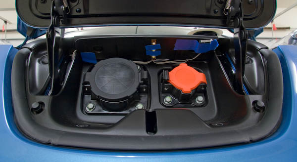
The switch in the upper right of the charge port area controls power to the circuit, turning off power when the door is closed.
The rest of this page explains what we did so that others can make similar modifications to their cars. Note that you'll need to be able to download a program to an Atmel AVR microcontroller.
We provide no warranty; proceed at your own risk!
Circuit
The circuit connects in the fuse box near the 12 V accessory battery and is unpowered while the charge port door is closed. When the door is opened, a lever switch connects power to the circuit. A microcontroller regulates power to the LEDs via a transistor, dimming the lights after 4.5 minutes, and then turning them off 30 seconds later, at which point the microcontroller enters a low-power sleep mode. The circuit draws 41 mA when the LEDs are lit (14 mA when dim) and 0.18 mA after they are shut off. (It would take over 7 months to drain 1 Ah at that rate!)
Once the lights are off, if we want them on again, we can just press and release the lever switch to power-cycle the circuit; the lights will come back on for another 5 minutes.
The components used here are parts that we had on hand; there are many options for the items used in this circuit.
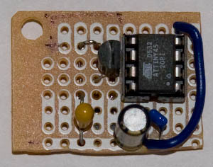
Here is an overview of the circuit:
- Power is supplied from the 12 V accessory battery through a standard automobile fuse.
- A lever switch activated by the charge port door controls whether the 12 V connection is
made to the rest of the circuit.
- The "normally closed" (NC) lead of the switch is connected to the 12 V supply.
- The "common" (C) lead of the switch is connected to the rest of the circuit.
- When the charge port door is closed, the switch is in the depressed position, which disconnects NC and C, breaking the circuit.
- When the charge port door is open, the switch connects NC and C, supplying power to the rest of the circuit.
- An optional toggle switch would provide a way to manually turn off power when the charge port door is open.
- When the door is open and the circuit is powered, the 12 V supply is routed two places:
- To the + connection on the LED strip.
- To the input of a voltage regulator. We're using 3.3 V, but anything from 2.7 to 5 V (with at least 25 V max input) is fine. The capacitors C1 and C2 are specified by the regulator. It would be better to have 10 μF for C2, but we had 47 μF available and it works OK.
- The ATtiny45 microcontroller uses the regulated (3.3 V) power. The capacitor C3 helps stabilize power. The output from the microcontroller goes to a transistor that switches the LEDs. (An ATtiny25 would work nicely here, too.)
- When the output from the microcontroller is high, the transistor will let current flow through the LEDs; when the microcontroller output is low, the transistor will break the LED circuit, turning off the LEDs. We used an NPN BJT; an N-channel MOSFET should work fine as well. The microcontroller cannot control the LEDs directly since the 12 V supply needed by the LED strip is outside the microcontroller's operating range.
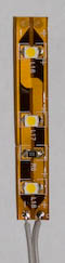
- The LED strip is a portion of a reel with repeating segments of 3 LEDs and a resistor (150 Ω in this case) in series. We're using one segment (3 LEDs).
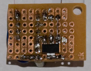
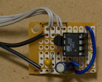
Here is the board built with what we had in our stash. The surface-mount component on the bottom
is the voltage regulator. They are available in through-hole versions, but this is what we had handy.
Program
The code is available in this ZIP (11 KB). It is distributed under the GNU General Public License.
We use the WinAVR development environment and avrdude downloader. There are resources elsewhere on the web for programming Atmel AVR microcontrollers; this page does not cover that.
The ZIP file will unzip as a folder (ChargePortLight) containing sub-folders with the code and compiled program.
The makefile assumes programming at ATtiny25 (even less expensive than the ATtiny45 we had on hand) and running at 3.3 V. If you use a different voltage, you can consider changing the brown-out detection voltage level (set to 2.7 V with the makefile's setfuse rule). See the makefile comments and MCU spec sheet for details.
To program an ATtiny25, you'll need to download PortLight.bin (from the Build folder) and
set the fuse bits using the command "make setfuse" (with the makefile
in the Source folder).
If you want to modify the code, there are comments in the source files that explain the program.
You can build with "make all" and download with "make
program".
Installation
Since our wires were routed through tight openings, we needed to make many of the solder connections at the car. We were able to connect the switch and LED strip to the ribbon cable ahead of time, but needed to wait to connect wires to the board and the fuse to the power wire, making those connections after the wire was routed in the car.
Preparation
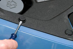
Under the hood, there's a plastic cowl over the front area, which is held in place with plastic "plugs."
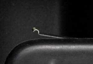
To remove each plug, we gently pried the inner disk up with small screwdriver (at one of two designated spots), just until it came free, about 1/4" – see the picture on the right. Then, we were able to grab the lower disc and pull it out gently, sometimes wiggling a small amount or using a small screwdriver; it was important not to pull up on the inner disk, just letting it "float" as we were removing the assembly from the hole.
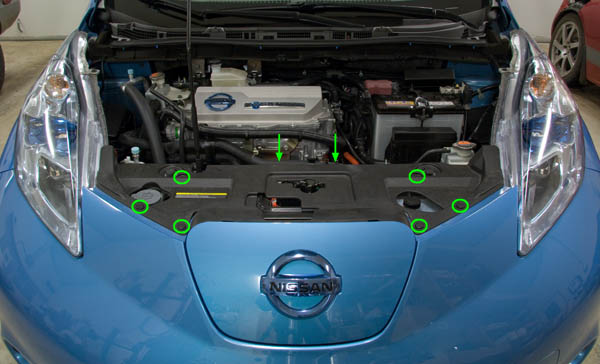
The picture below shows the locations for the 8 plugs holding the cowl in place, 6 on the top surface
(circles) and 2 on the rear vertical surface (arrows).
LED Strip and Switch
We were able to solder the LED strip and switch to the ribbon cable before installing them into the car. Since our LED strip was specified as non-waterproof, we coated its exposed metal with conformal. Clear nail polish is a fine substitute if you don't happen to have a can of conformal lying around. :-)
We decided to route wires into the charge port area through the hole for the cable release cord, which is in the lower left of the charge port's left-hand hinge area. We were able to trace the cable release cord's path through the (now-uncovered) area at the front of the under-hood area, and found it entering the charge port on the left side. By shining a light aimed at the back of the hole with the cable release cord, we were able to get a nice target for feeding the ribbon cable from the charge port area.
There's very little clearance above the ports, so we decided to see if just a single strip of 3 LEDs mounted between the ports provided enough light; it did, and in fact was brighter than we needed (which we took care of by dimming the lights in the software).
It was tempting to put the switch on the left side, near where the wire entered the charge port area, but we realized that it would interfere with the DCQC port's cap! Fortunately, it fits nicely on the right side since the J-1772 connector is smaller.
Since we wanted to test our circuit before doing a final installation,
we taped the LED strip and switch into place using blue architect tape, which does a nice job
of holding temporarily and not leaving a residue.
We fed the ribbon cable along the back of the charge port ceiling and then into the left-side hinge area,
taping it along the right-hand side (there's a slight flange here that can help hide it), and
routing it toward the bottom of the hinge area. We wanted to have it taped near the bottom
so it didn't get caught by the hinge.
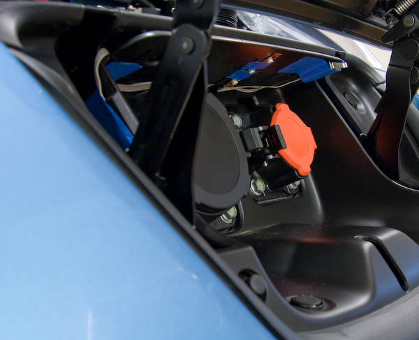
The picture on the right shows how much the lever sticks out (viewed from above). We positioned it so that the "box" was fully under the overhang, with the lever sticking out as much as possible; when the lever is pressed in, it is parallel with the edge and completely under the overhang. The architect tape was great for experimenting with the optimal placement.
Later, after installing the board and verifying that everything was working well and we liked the placement of the items, we mounted items permanently. The LED strip has an adhesive on the back, we used Stampin' Up! Sticky Strip to hold the lever switch, and we replaced the architect tape with black gaff tape.
Battery Connection
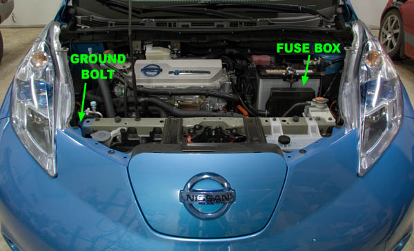
This picture shows the locations of the fuse box (power connection) and ground bolt.
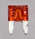  |
We put a 10A mini-blade automotive fuse in a vise, then used a hack saw to make a small notch as shown in the picture on the right.
When we shined a flashlight into the fuse box, we could see a small triangle of light at the top front corner of the outlet cord on the right. It was just large enough that we could push a small wire in from the outside. We retrieved it using a long pair of tweezers and one of those spring-loaded part grabbers.
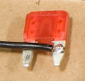
After feeding the wire into the fuse box, we stripped the end and placed it into the notch on the fuse and soldered it (on both sides).
The DTRL spot in the fuse box has a connection to the positive battery lead. The other side of the fuse socket has no connection, leaving a nice bit of space for our modified fuse. Note that we needed to make sure that we plugged it in with the "clean" leg toward the front of the car, plugged in to the connector (and the modified leg in the open area).
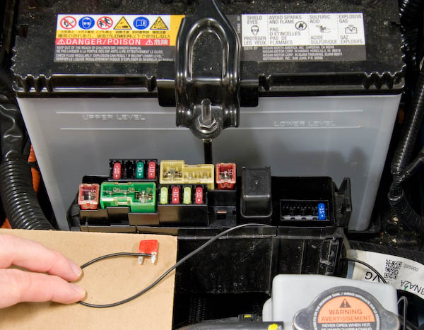
This picture shows the fuse box and fuse after feeding the wire into the box and soldering the
fuse to it. Note the wire exiting the box near the lower right corner; it's over the white label.
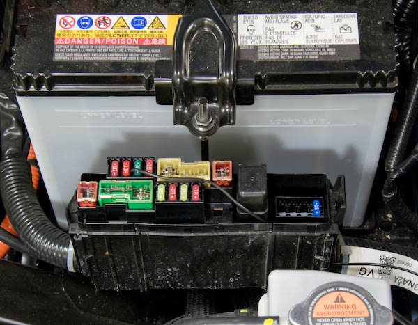
This picture shows the fuse box with our fuse plugged in.
From the bottom of the fuse box, we routed our power wire along the cord-release for the charge port door, fastening with zip ties in a few places.
Circuit Board
We soldered the wires to the board after routing them to the desired spot in the car. The black pair is power (white stripe designates ground wire) and the 4 gray wires are the ribbon cable connected to the LEDs and switch.
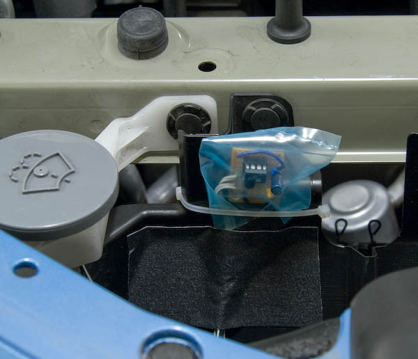
We wrapped the board in an antistatic bag and taped it shut with gaff tape, then mounted it to
the car with a couple zip ties, and held it into place with more gaff tape.
Ground Connection
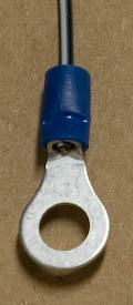
We crimped a ring onto the ground wire and connected it to a bolt on the left side of the car, which you can see Tom working on here.

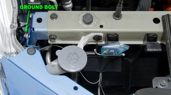
The picture below shows the locations where we installed the board and connected to a ground bolt.
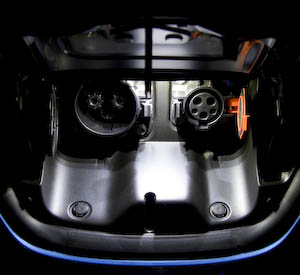
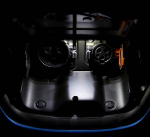
These photos show what the light looks like in a dark garage. The picture on the right is when the
lights dim after 4.5 minutes.
| Electric Vehicles | Overview | FAQ | Efficiency Analysis | Driver Resources |
|
©1996-2026 Tom and Cathy Saxton. You may not copy or reproduce any content from this site without our consent.